

Introduction
In creating an analysis model using Femap, you frequently have to place line elements such as beams between nodes. However, repeating this work by hand is time-consuming and tends to cause mistakes. Therefore, let’s use Excel VBA to automate the process and greatly improve the efficiency. In this article, we will explain how to automatically generate beam elements between two nodes by utilizing Femap’s API.
Code to create beam element between two nodes
First, nodes and properties must be created before the beam element can be created.
See the following article for information on how to automatically create nodes.

We also offer a variety of automatic property creation services, so please look for them in the Links section.

The following is an example of code that creates a beam element between two nodes.
This example creates a beam element (element ID=1) with node ID1 and node ID2 as endpoints and a beam property ID of 1.
Sub CreateBeamElementInFemap()
  'Create a Femap model object
  Dim f As Object
  Set f = GetObject(,"femap.model")

  'Create an element object
  Dim el As Object
  Set el = f.feElem

  'Define a linear beam element
  el.Type = 5 'Set to 5 for a linear beam element
  el.propID = 1 ' Property ID for the beam element
  el.topology = 0 'lement topology; set to 0 for a line
  el.orientID = 0 'Orientation node ID for bar or beam elements. Set to 0 to define orientation using the orient vector.
  el.orient(0) = -1 'X-component of the orientation vector (Double type)
  el.orient(1) = -1 'Y-component of the orientation vector (Double type)
  el.orient(2) = 0  'Z-component of the orientation vector (Double type)
  el.Node(0) = 1 'Starting node ID
  el.Node(1) = 2 'Ending node ID
  'Create or overwrite the element with the specified ID
  el.Put(1) 'Element ID to create or overwrite

  'Release the objects
  Set el = Nothing
  Set f = Nothing

End Sub- Lines 4-5 create the Femap object; note that executing this code when FEMAP is not running will result in an error.
- Lines 8-9 create the element object of the Entity object.
- Line 11 specifies the element type, which is entered as a Long type. For a linear beam element, enter “5.
- The 12th line specifies the property ID.
- The 13th line is the element shape setting. 0 is for line (line).
- Lines 14 to 17 are for inputting the element orientation direction. If the element is specified by a node, enter the ID in the orientID field. If the element is not specified by a node, enter each value in the orient array with orientID=0.
- Lines 18-19 specify the node IDs that will be the starting and ending points of the beam elements.
- Line 21, the .Put() method is used to create a new element and overwrite it.
Example of linking to an Excel sheet
Example of creating a beam element from values entered in an Excel sheet
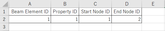
Prepare the following table in Excel.
Columns A2 to D2 are input columns.
Sub CreateBeamElementInFemap()
  'Create a Femap model object
  Dim f As Object
  Set f = GetObject(,"femap.model")

  'Create an element object
  Dim el As Object
  Set el = f.feElem

  'Define a linear beam element
  el.Type = 5 'Set to 5 for a linear beam element
  el.propID = Cells(2, 2) ' Property ID for the beam element (read from cell B2)
  el.topology = 0 'Element topology; set to 0 for a line
  el.orientID = 0 'Orientation node ID for bar or beam elements. Set to 0 to define orientation using the orient vector.

  'Define the orientation vector for the beam or bar element
  el.orient(0) = -1 'X-component of the orientation vector (Double type)
  el.orient(1) = -1 'Y-component of the orientation vector (Double type)
  el.orient(2) = 0  'Z-component of the orientation vector (Double type)

  'Assign node IDs for the start and end points of the element
  el.Node(0) = Cells(2, 3) 'Starting node ID (read from cell C2)
  el.Node(1) = Cells(2, 4) 'Ending node ID (read from cell D2)

  'Create or overwrite the element with the specified ID
  el.Put(Cells(2, 1)) 'Element ID to create or overwrite (read from cell A2)

  'Release the objects
  Set el = Nothing
  Set f = Nothing

End Sub
Example of outputting beam element information to an Excel sheet
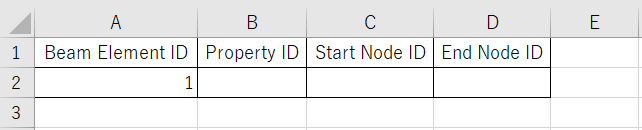
Prepare the following table in Excel.
A2 is the input column and B2 to D2 are the columns where the obtained values are entered.
Sub GetBeamElementInFemap()
  'Create a Femap model object
  Dim f As Object
  Set f = GetObject(,"femap.model")

  'Create an element object
  Dim el As Object
  Set el = f.feElem

  'Retrieve a linear beam element
  el.Get(Cells(2, 1)) 'Specify the element ID to retrieve (read from cell A2)
  Cells(2, 2) = el.propID 'Get the property ID of the element
  Cells(2, 3) = el.Node(0) 'Get the starting node ID
  Cells(2, 4) = el.Node(1) 'Get the ending node ID

  'Release the objects
  Set el = Nothing
  Set f = Nothing

End Sub
Conclusion
This article showed how to create a linear beam element between two nodes of a Femap using EXCEL VBA. By using the code, you can greatly reduce the time and effort of manual work, as well as help prevent mistakes. We encourage you to try applying this code to create more efficient analytical models!
Connecting nodes to create beams? That’s what I call building strong connections!

コメント